Majority vote project
For this project, the class was tasked with designing a circuit that would display a "yes" answer to a vote given multiple conditions. There were a total of four people voting in the scenario - a President, Vice-President, Secretary, and Treasurer. Each person voted once. If there was a tie, the President's vote was the deciding factor. If 3 people voted "yes" than that would be the outcome. The constraints on this project were that we were only allowed 2-input gates while putting the circuit together and we were only given a limited amount of time in class to complete the assignment. The following report will explain how I came to the working circuit and what steps were taken.
Truth table and un-simplified logic expression
A truth table is used to describe when a solution will work or not given multiple variables. To create the table, each column is created using binary code. The first column alternates between 0 and 1, each repeated once, because it is the first column. (0,1,0,1,0...) The second column repeats 0 and 1 twice in a row respectively. (0,0,1,1,0,0,1,1...) In the situation presented, each 0 is a vote of "no" and each one is a vote of "yes."
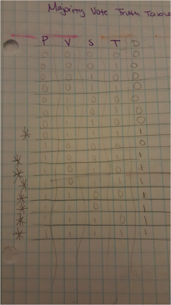
Given the directions on how each vote is to be determined, I then came up with each "yes" outcome of the table. The un-simplified expression is as follows, given in Sum-of-Products form to read easily:
D= P'VST+PV'S'T+PV'ST'+PV'ST+PVS'T'+PVS'T+PVST'+PVST
D= P'VST+PV'S'T+PV'ST'+PV'ST+PVS'T'+PVS'T+PVST'+PVST
Un-simplified circuit (Multi-Sim)
The following is a circuit diagram for the aforementioned un-simplified logic expression. It has 35 gates, each having one of 3 different functions. The first four on the left are invertors, the large batch in the middle are known as "AND" gates and multiply outcomes together, and the last set all the way to the right are known as "OR" gates and add outcomes together. Everything is connected to a bus, powered, and grounded.
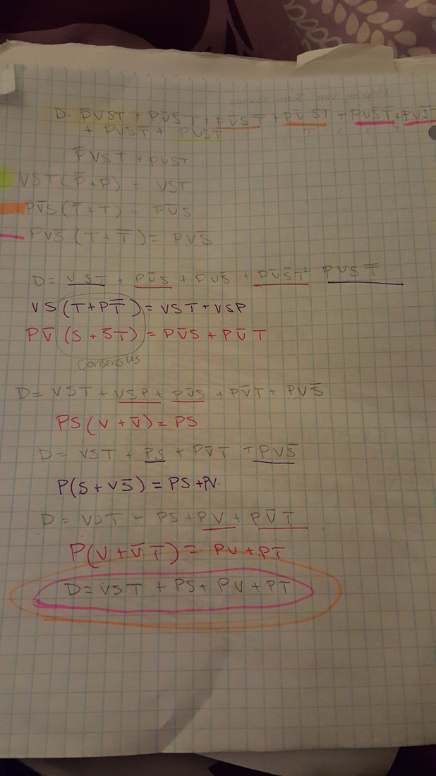
Boolean algebra simplification
The method by which one uses to simplify the long logic expression given above is known as "Boolean Algebra." It involves the difficult process of grouping variables and simplifying them using the laws of the algebra. Below is the simplified expression and the Algebra to get there.
D= VST+PV+PS+PT
D= VST+PV+PS+PT
sIMPLIFIED CIRCUIT
Now that we have the simplified logic expression, we can build an equivalent circuit using less gates and less resources in general (wires, bus space, etc). The following is a simplified diagram, built in the computer program MultiSim, and much easier to follow. It uses 8 gates, each performing one of two functions. The left ones are "AND" gates and the ones for to the right are "OR" gates. Therefore, the circuit contains 27 less gates than the previous diagram, meaning it is more efficient because it does the same job with less materials.
Bill of materials
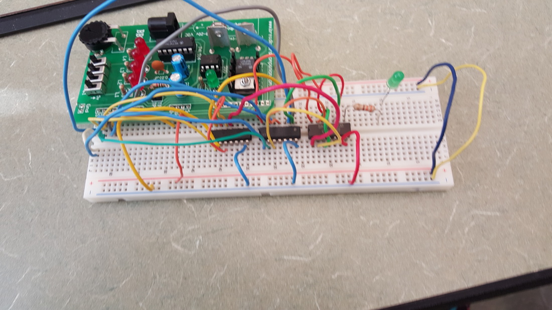
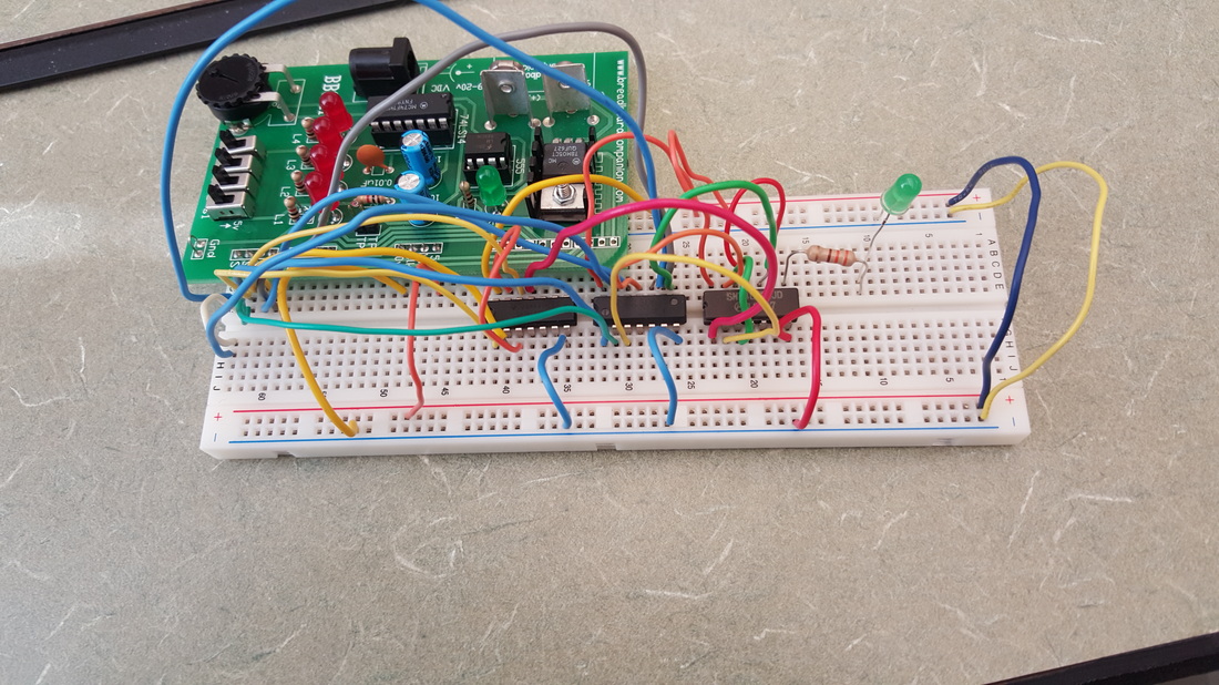
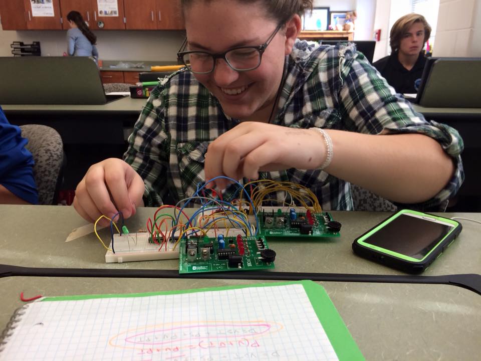
breadboarding
Finally, we are able to take the simplified diagram and build a working breadboard prototype. I learned a lot about building this, most importantly: it's not the board's fault if it doesn't work. Most of the time spent building this board was actually troubleshooting when it didn't work. Wires were moved, chips were grounded and powered, and components were switched out. The pictures below are the finished product, as well as me in the middle of building said finished product.