Design Brief
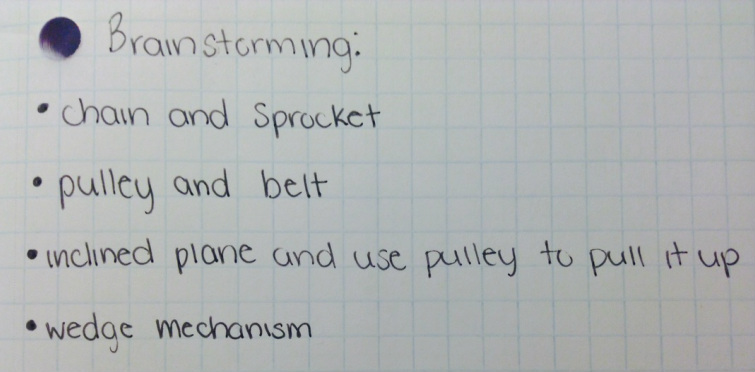
Brainstorming List
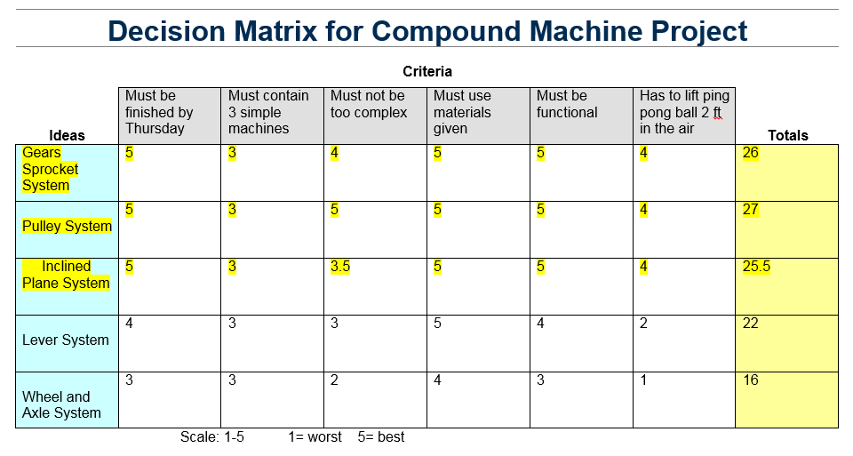
Decision Matrix
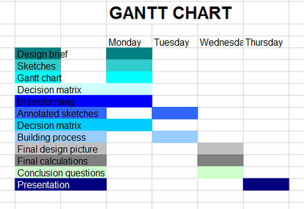
Gantt Chart
Preliminary Sketches
Building Process, Testing Results, and Modifications
When we were first assigned the project, Erin had been out of school due to medical reasons. As of such, Matt and I started the project on our own. It was Matt who came up with our original idea, and from there we simply built upon that. We began with the idea of using an inclined plane, but after some words of the wise (AKA Mrs. Harlan) we changed this idea. Rather than have the inclined plane hold the sprockets, we replaced it with a gear and sprocket system. While this certainly made the machine more efficient, we here encountered a problem. The sprocket would continuously fall off of the top gear. I later discovered that this was because the gears weren't aligned and quickly remedied the issue.
At this point, we only have one machine, however, the requirements called for three. As of such, we came up with the idea that we could attach a weight to the sprocket system and let it fall - thus creating a pulley. While this idea (surprisingly) worked, we were still down one machine. For a while, we were stumped. What could we add? More words of the wise lead us to the machine we have now - a gear train with a lever. These two machines replaced our pulley idea and finally gave us the correct amount of machines to meet the requirement.
At this point, we only have one machine, however, the requirements called for three. As of such, we came up with the idea that we could attach a weight to the sprocket system and let it fall - thus creating a pulley. While this idea (surprisingly) worked, we were still down one machine. For a while, we were stumped. What could we add? More words of the wise lead us to the machine we have now - a gear train with a lever. These two machines replaced our pulley idea and finally gave us the correct amount of machines to meet the requirement.
Final Design Picture & Sketch with Annotation
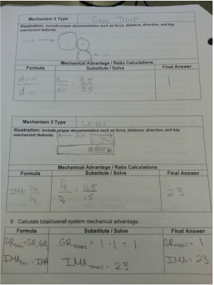
Final Calculations
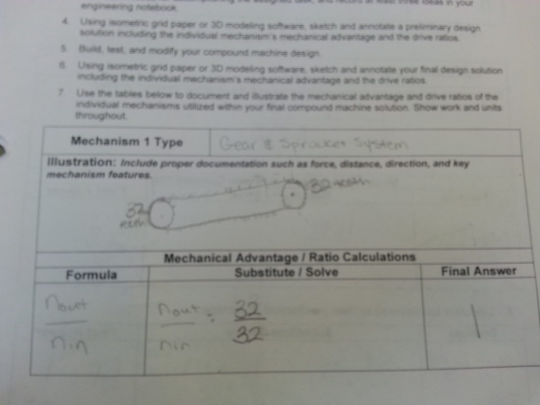
|
|
Conclusion Questions
1.) For which mechanism was it the easiest to determine the mechanical advantage or drive ration? Why was it the easiest?
The gear train was the easiest because idler gears (or gears that aren't the input/output) don't effect the gear ration.
2.) For which mechanism was it the most difficult to determine the mechanical advantage or drive ratio? Why was it the most difficult?
The lever was the most difficult because it required a different formula than the gear and sprocket & gear train.
3.) At what value would you estimate the input and output forces of your compound machine? How did you arrive at your estimated values?
I would arrive that the input value would be less than the output value because if the MA is greater than 1, then less effort force is required.
4.) What modifications could you make to your compound machine to make it more mechanically efficient?
A longer lever would be more efficient because it would require less effort force.
