60 second timer
allie burton
12/16/15
Project overview
For this project, we were tasked with creating a counter using two inputs and two outputs. The inputs were the clock and reset signal, and the outputs were the ones and tens digit displays. after reaching 59, the counter will detect 60 and reset to 00 and begin counting once again. We built this counter using synchronous SSI and MSI (JK flip flops and a 74LS163 MSI counter).
PLD CIRCUIT
Like the previous project, we had to create a circuit using both SSI and MSI that with a reset switch so after detecting a certain number, the counter would reset to 00 and begin counting again. However, this was different because we were using a synchronous logic with JK flip-flops and a 74LS163 counter.
Final project conclusions
1.) Synchronous circuits are all hooked to the same external clock. Asynchronous circuit components are connected to each other, then to a clock.
2.) The '163 counter stops at the number detected and can only be an up counter. The '193 counter can be both an up and down counter, but stops at the number after the detected one.
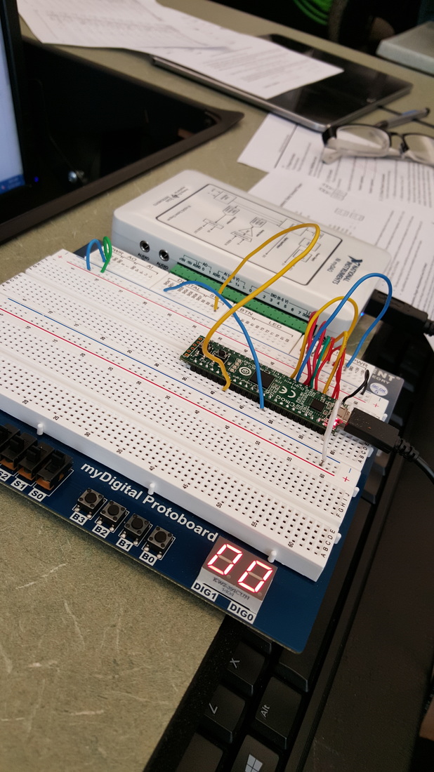
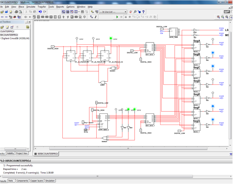
3.) To build the timer, the first thing I did was analyze the constraints given. We had to use JK flip flops for the tens digit, and since the timer needed to count from 00 to 59, I knew that the flip flops would have to detect a 6 to reset. This means that from the start, I knew I needed 3 JK flip flops. From there, I read through the constraints on the ones digit. We had to use the MSI counter, and since this had to count from 00 to 09, I didn’t create a start value (so it would start at 00 automatically). The counter detects a 9 and resets to 0 because the counter used, the 74LS163, resets immediately after the detected number, unlike other counters that have to detect a number higher. After that, I thought about how to connect the clock to both circuits. The clock connects to the 163 counter, and the reset from that counter then connects to the flip flops. This is so that the timers are in sync and the tens digit counter will count when the ones digit counter resets. In between them, I have a reset switch that will clear the count after it detects 60. This reset switch was created by connecting an AND logic gate to the reset of the tens digit circuit and the load of the ones digit circuit. Finally, I assigned the pins to the necessary components. The clock was assigned to pin 14 and I assigned the reset switch to pin 7. Wiring the board was easy from there, all you have to do is connect the display letters to the pins given, hook up the clock and reset witch, then power/ground the board.
4.) From what I can see, everyone else's circuit was the same as mine. Perhaps some pin assignments were different, but nothing outside of that.
2.) The '163 counter stops at the number detected and can only be an up counter. The '193 counter can be both an up and down counter, but stops at the number after the detected one.
3.) To build the timer, the first thing I did was analyze the constraints given. We had to use JK flip flops for the tens digit, and since the timer needed to count from 00 to 59, I knew that the flip flops would have to detect a 6 to reset. This means that from the start, I knew I needed 3 JK flip flops. From there, I read through the constraints on the ones digit. We had to use the MSI counter, and since this had to count from 00 to 09, I didn’t create a start value (so it would start at 00 automatically). The counter detects a 9 and resets to 0 because the counter used, the 74LS163, resets immediately after the detected number, unlike other counters that have to detect a number higher. After that, I thought about how to connect the clock to both circuits. The clock connects to the 163 counter, and the reset from that counter then connects to the flip flops. This is so that the timers are in sync and the tens digit counter will count when the ones digit counter resets. In between them, I have a reset switch that will clear the count after it detects 60. This reset switch was created by connecting an AND logic gate to the reset of the tens digit circuit and the load of the ones digit circuit. Finally, I assigned the pins to the necessary components. The clock was assigned to pin 14 and I assigned the reset switch to pin 7. Wiring the board was easy from there, all you have to do is connect the display letters to the pins given, hook up the clock and reset witch, then power/ground the board.
4.) From what I can see, everyone else's circuit was the same as mine. Perhaps some pin assignments were different, but nothing outside of that.
