DMV Dispaly project
allie burton
12/8/15

Project overview
In this project, we were tasked with creating a digital counter that would count from 00-80. To do this, we had to use all of our previous knowledge on asynchronous counter to first build the circuit in Design mode on MultiSim, then PLD mode.
Multisim & PLD circuit
Above are pictures of the circuit in design mode and PLD mode. Design mode is how we start building our circuits and uses the 74LS code numbers to identify logic gates. In PLD mode, we build the circuit similarly, but the logic gates are titled by their function and pin number (NAND4, AND2). We also use this mode to export our circuit onto a chip and breadboard it to visually see what is happening. When our chip is uploaded, we breadboard based on the input/output pin assignments that were put in the PLD design.
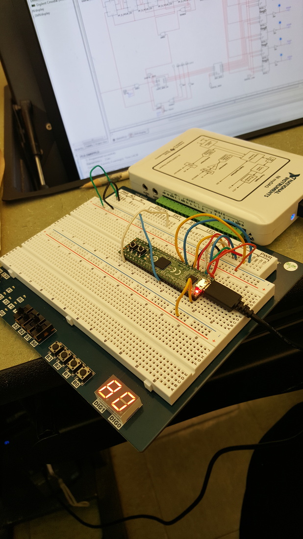
Bill of materials
- Breadboard
- Chip for uploading
- MyDaq reader to display HEX display
- Wires on the board
- USB connectors
final project conclusions
SSI - Small Scale Integration, demonstrated in the tens digit (top part) of the circuit
MSI - Medium Scale Integration, demonstrated in ones digit circuit
Medium Scale Integration limitations include only being able to start counting from 0 and only being an up counter.
The term "ripple effect" comes from the pause in between counting while the circuit is performing the action. The numbers will flicker for a second because each flip-flop must wait for the response of the one before it.
How the circuit works:
The top part (tens place) uses SSI with D flip-flops. The signal travels through each one, and using logic gates, it detects the number at which to stop. Because we want to see 8, it must detect 9 (1001 in binary) to clear there rather than 8. In this project, it must also detect 8 and connect to the bottom circuit so that it will pause at 8, rather than reset afterwards. The second half uses MSI and will count 0-9 repeatedly.
