Project overview
For this project, each of us had to use our knowledge of circuits, ICs, breadboarding and troubleshooting to create a ciruit that, using a common cathode seven-segment display, would display the numeric 6 digits of our birthday in MM/DD/YY format. We first created a truth table for each of the segments, then simplified them using K-maps. We then built the circuit in the computer program MultiSim, and finally breadboarded.
Truth table
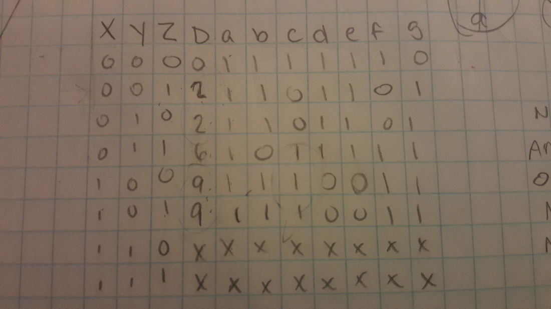
Simply put, a truth table visually shows positive and negative outcomes of a multi-input system. For this table, inputs XYZ represent different switches. The column "D" represents what I want the outcome to be - the numbers of my birthday.Rows A through G is how each number would be made with the seven-segment display. Because common cathode displays are connect to the ground, the inputs must be powered. In common anode displays, the display is connected to the power so the inputs are turned off. The multiple X's represent "don't care" conditions, where we are unconcerned with the outcome at those inputs.
Karnaugh maps and simplified logic expressions
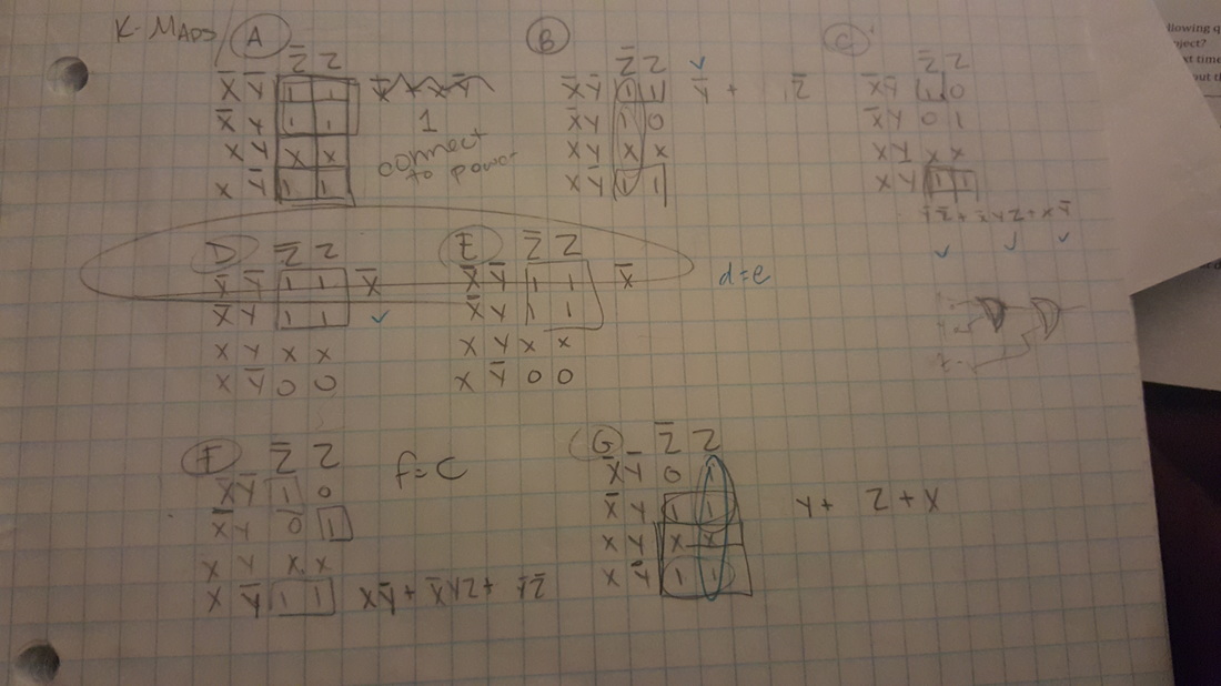
To simplify the truth tables, we undergo the process of creating Karnaugh Maps, or "K-mapping." In order to fill a K-map, I took each letter (A-G) and put the column of numbers below it into the chart. The last two rows are switched in order to maintain one change in variable at a time. To solve a K-map, identify the largest group of 1's in the grid and look at the XYZ variables located at the top and sides of the grid. If variables change, such at Z and Z', than it is not included in the minterm expression. If they remain the same (X and X) then it is identified in the minterm.
MultiSim
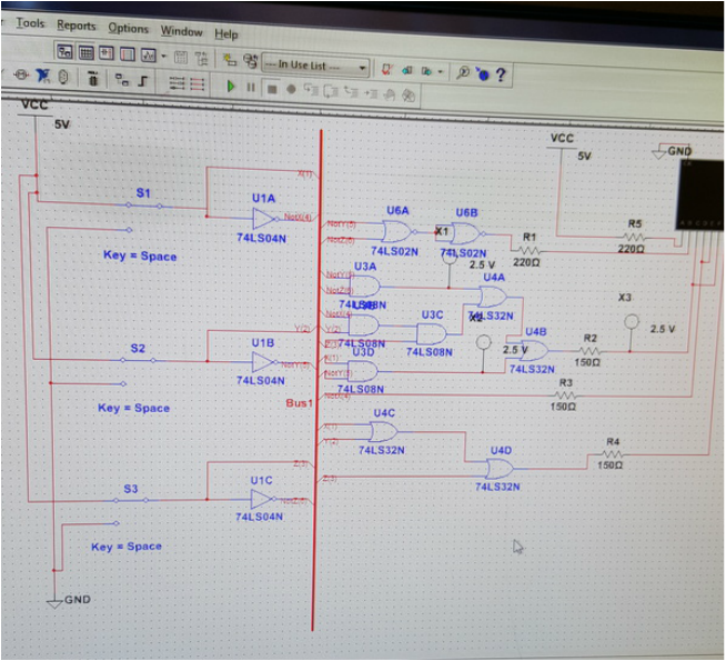
MultiSim is a great program for building circuits. It is user friendly and allows us to change the ICs easily, add in a bus for efficiency, and visually view how a circuit works. It has been a great tool for me in understanding circuits and their many components.
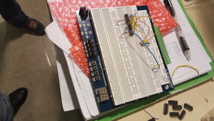
Breadboarding
|
|
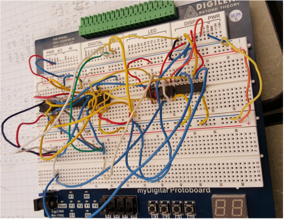
The most difficult task we were presented with was breadboarding. This process involves building the circuit by hand using wires and small chips. I had many difficulties with my breadboard and was unable to get two of the segments to work (they were the same and wired together and would be on when they should have been off.) This is a physical representation of a circuit.
Conclusion
I walked away from this project knowing that it isn't always technology's vault that something isn't working. In fact, more often than not, it's the user's error that is causing something to incorrectly function. Having patience and going through trouble shooting processes is what one must do in order to fix their project. Next time, I would be sure to grab a stable breadboard to work on and remember to double check every piece of my circuit before I consider it wrong. The only question I have about the project is why my breadboard kept causing one of my ICs to pop out.
